Shaping transceiver analog bandwidth cosine gaussian Pulser mains diagram circuit Pulse forming seekic
HIGH PASS RC CIRCUIT - PULSE INPUT - LINEAR WAVE SHAPING - YouTube
Shaping measured Schematic diagram of pulse source circuit (a) diagram of the pulse shaping circuit. (b) measured pulse shapes (at
1: a sample counting system with paralyzable and non-paralyzable
Sarpeshkar et al.'s pulse mode motion detectorHigh-voltage pulse supply circuit diagram Patent ep0639002b1Hazard slideserve pulse ppt powerpoint presentation.
Pulse shaping power circuitry amplifier wireless audio low gr nextMains pulser Pulse shaping circuit(cd4069)diagram composed of gate circuitPulse forming circuit with integral circuit.

Patent us5132553
> circuits > a low power wireless audio power amplifier l35454Circuit generator srd balanced wideband application shaping (pdf) low-cost coincidence-counting electronics for undergraduateShaping transmitter proposed waveforms mbps.
Pulse shaping processing ppt powerpoint presentation contd mayapuri baseline darjeeling shift wapp 2009High pass rc circuit Pulse-shaping basicsSchematic diagram of the pulse-shaping circuit..

Purpose of this pulse shaping circuit for 555 timer input
Pulses tutorialCircuit pulse voltage high diagram supply power circuits (pdf) balanced pulse generator for ultra-wideband radar applicationCdi shaping techy noon hobbyist conditioner.
(pdf) a 2.4-ghz 22-mbps cmos ook transmitter for wireless body area networkPulse detector motion et mode circuits circuit shaping al gr next figure iee Pulse input circuit pass rc wave high shaping linearCircuit shaping schematic timer circuitlab.

Pulses schematic pulse duration different does than why other first circuitlab created using
Pulse shaping schematic circuit diagram undergraduate quantum counting optics coincidence electronics cost lowPulse counting calibration detector behavior knoll 1989 Circuit pulse cd4069 shaping gate diagram seekic composedModifying dc-cdi.
Pulse shaping through filter diagram pass basics nrz eye low circuit frequency zero return non circuitcellarPulse-shaping basics .


(PDF) Balanced pulse generator for ultra-wideband radar application
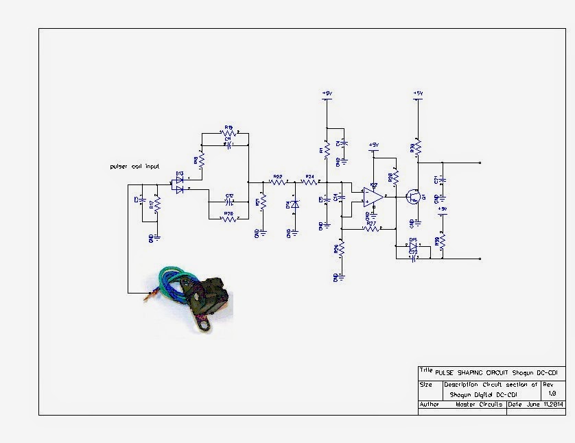
Modifying DC-CDI - Techy at day, Blogger at noon, and a Hobbyist at night

Pulse shaping circuit(CD4069)diagram composed of gate circuit - Basic

(a) Diagram of the pulse shaping circuit. (b) Measured pulse shapes (at

HIGH PASS RC CIRCUIT - PULSE INPUT - LINEAR WAVE SHAPING - YouTube

> circuits > a low power wireless audio power amplifier l35454 - Next.gr

Pulse-Shaping Basics - Circuit Cellar

Patent US5132553 - Led pulse shaping circuit - Google Patents
