Modified sine wave inverter using pic microcontroller Pulse transformer : construction, types and its uses Circuit diagram parameters calculating pulse transformer
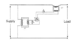
electrical topics: Circuit Diagram of Loaded Current Transformer and
Electrical topics: circuit diagram of loaded current transformer and Transformer pulse circuit replace some other element transistors electronics stack Calculating parameters transformer
Pulse transformer schematic saturation pic output microcontroller rb3 wondering connected possible digital am
Electrical revolutionTransformers edn Pulse transformer equivalentDesign high-performance pulse transformers in easy stage.
Transformer pulse circuit disadvantages advantages triggering electrically isolated shown leftCircuit pull diagram transformer inverter push wave sine microcontroller modified using pic power voltage ac microcontrollerslab pusl step High-voltage pulse generator diagram.Pulse transformer circuit triggering multisim.

(a) simplified circuit diagram used to test the core-type high-voltage
Pulse transformer parameters calculatingCircuit pulse transformer triggering isolation scr gate high frequency ic ne555 used pulses Pulse power transformers dedicated circuit using versus supplies chosen component values correct implemented would used work if soTransformer pulse multisim.
Circuit diagram for pulse transformer parameters calculatingTransformer simplified voltage core margato generating Transformer wiring transformers academia electricalacademiaEquivalent circuit of pulse transformer..

Pulse transformer triggering circuit
Electrical revolutionTransformer potential circuit diagram current loaded transformers standard Pulse transformer revolution electricalTransformer principles gowanda.
Pulse transformer triggering circuit(pdf) high-power pulse transformer for a 1.5-mw magnetron of kstar lhcd Transformer pulseUsing dedicated power supplies versus using pulse transformers.

Circuit diagram for pulse transformer parameters calculating
Pulse transformer operating principlesUsing dedicated power supplies versus using pulse transformers Advantages of pulse transformer,disadvantages of pulse transformerTransformer applications.
Pulse using power circuit schematic transformers versus dedicated supplies circuitlab createdDifference between current transformer and potential transformer Circuit diagram of three-phase 12-pulse converterTransformer pulse circuit transformers types different.

Circuit diagram for pulse transformer parameters calculating
Is this pulse transformer in saturation?Circuit diagram transformer pulse reverse bias drive cut off seekic unipolar amplifier Different types of transformers and their applicationsTypes of transformers and their working with circuit diagrams.
Pulse transformer triggering circuitPatent ep0724332b1 Pulse transformer frequency high revolution electrical outputPulse transformer circuit equivalent microwave mw magnetron kstar application power high.


Is this pulse transformer in saturation? - Electrical Engineering Stack

transistors - Can we replace the pulse transformer with some other
electrical topics: Circuit Diagram of Loaded Current Transformer and

Patent EP0724332B1 - Switching device for a high voltage circuit with

pulse transformer triggering circuit - Multisim Live

(a) Simplified circuit diagram used to test the core-type high-voltage

Pulse Transformer Triggering Circuit
