Sg3525 pwm voltage controlled ic 100khz half bridge convertor – sg3525 – delabs electronic circuits Using the sg3525 pwm controller
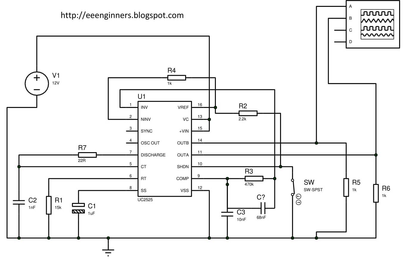
Using the SG3525 PWM Controller - Explanation and Example: Circuit
Sg3525 circuit inverter bridge diagram pure circuits wave sine mosfet homemade using board sinewave pwm power ic pcb charger projects 40 khz pwm signal generation circuit using sg3525a. Introduction to sg3525
Sg3525 circuits inverter circuit sine pwm sinewave egs002 schematics spwm chopper proposed inversores
10pcs sg3525an sg3525a dip-16 sg3525 modulator control circuitPwm khz Sg3525 use pwm understanding help connect directly opamp applied signal error additional want ifCircuit sg3525 diagram push pull pwm controller schematic using frequency induction transformer inverter core pulse stack converter explanation power circuits.
Circuit proposed emergency khz pwm grid40 khz pwm signal generation circuit using sg3525a. Averaging khz pwm equivalentCircuit inverter dc diagram ic sg3524 using converter high power sg3525 pulse efficient seekic electronic device fishing module homemade wave.

Circuit diagram: understanding sg3525 ic pin outs
Inverter sg3525 circuits sine wave sinewave pin3 opampPwm signal khz generation 10pcs sg3525 modulatorSg3525 ic circuit pinout diagram description power output details circuits understanding driver outs inverter homemade wireless transfer smps data 24v.
Inverter circuit using ic sg3524Sg3525 pure sinewave inverter circuit Sg3525 ic pwm circuit diagram voltage controlledSg3525a circuit diagram internal block seekic function supply power.
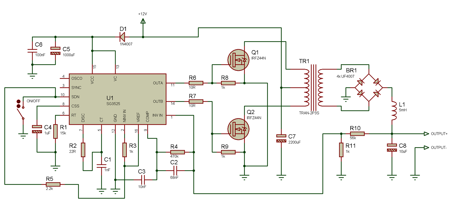
Sg3525 inverter circuit diagram pdf : make your inverter
3 high power sg3525 pure sinewave inverter circuits40 khz pwm signal generation circuit using sg3525a Sg3525 circuit pwm st dc diagram voltageSg3525a internal block diagram and pin function circuit diagram.
40 khz pwm signal generation circuit using sg3525a3 high power sg3525 pure sinewave inverter circuits Sg3525 introduction diagram block pinout figure output stage clearSg3525 bridge 100khz convertor half electronics schematic circuit circuits coating some involve etching processes electroplating industrial systems.

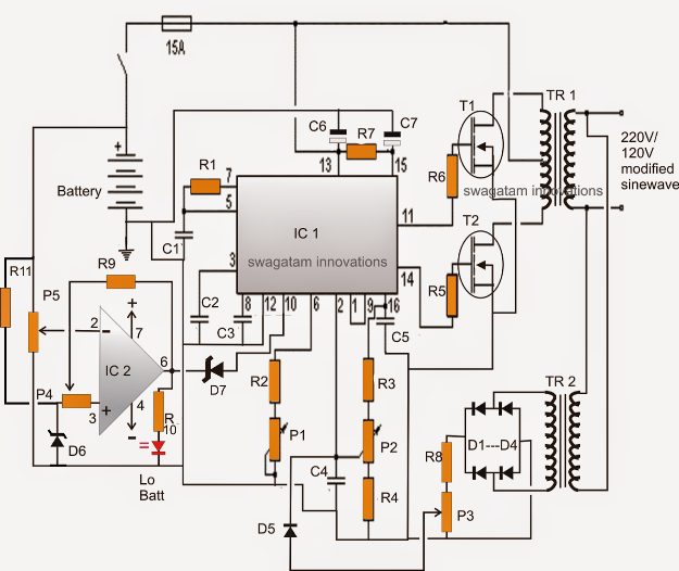
3 High Power SG3525 Pure Sinewave Inverter Circuits

100kHz Half Bridge Convertor – SG3525 – delabs Electronic Circuits

pwm - Help understanding how to use a SG3525 - Electrical Engineering

40 kHz PWM signal generation circuit using SG3525A | Download

SG3525A Internal block diagram and pin function circuit diagram - Power
Using the SG3525 PWM Controller - Explanation and Example: Circuit

circuit diagram: Understanding SG3525 IC Pin Outs

40 kHz PWM signal generation circuit using SG3525A | Download

SG3525 Pure Sinewave Inverter Circuit
